Context & Engineering Objective
Electrodynamic dust shields can repel lunar regolith from charged surfaces, but most laboratory characterization keeps the EDS film stationary. Future applications such as spacesuit joints, inflatable habitats, and deployable structures will bend and stretch the film while it operates. Team FLEX therefore designed a mechanism that could introduce repeatable mechanical deformation while the sample remained inside a dusted vacuum environment.
The objective was not simply to make a bending fixture. The rig had to fit within approximately 180 mm of chamber clearance, coexist with the dust shaker and camera, avoid lubricants and high-outgassing materials, electrically isolate the active film, and retain a path to remotely controlled cycling and strain measurement.
Role & Project Scope
This one-semester ME 6102 team project covered user and stakeholder research, requirements definition, concept generation, down-selection, analytical feasibility, CAD, preliminary FEA, and a non-functional physical mockup. I corresponded directly with the actuator manufacturer to investigate ASTM E595/E1559 outgassing compatibility. Full machining, vacuum-chamber integration, dynamic testing, and EDS performance measurement were outside the course scope.
- Fit a modular mechanism within the approximately 180 mm internal clearance of the reference vacuum chamber
- Support bending, stretching, and wrinkling without obstructing the dust shaker or camera line of sight
- Select low-outgassing metals, fasteners, springs, cables, and an FFKM electrical-isolation layer
- Control film deformation without exceeding the safe strain range or introducing sudden clamp loads
- Preserve a pathway to automated cycling and image-based strain measurement inside the sealed chamber
Methodology
The team first translated customer interviews and the chamber interface into measurable requirements. A function tree, black-box and four-box models, and a House of Quality clarified what the rig had to deform, constrain, measure, and avoid. Divergent concepts were generated using 6-3-5, morphological combinations, bio-inspired searches, TRIZ, patent review, and benchmarking.
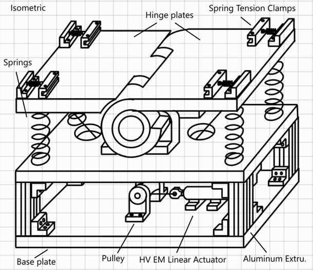
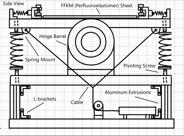
Two rounds of down-selection were necessary. An initial Pugh evaluation favored biaxial cable stretching, controlled bending, and mandrel concepts. Faculty feedback then shifted the emphasis toward multifunctionality, modularity, and genuine high-vacuum compatibility. The final direction was a spring-loaded hinge driven by a vacuum-rated electromagnetic linear actuator, with a two-cable linkage converting a 25 mm stroke into symmetric plate rotation.
- Designed two large-radius hinge plates around a central pin, with four spring clamps that hold the EDS film and restore the parallel position
- Added an FFKM sheet to electrically isolate the EDS sample from the metal hinge plates and allow alternate surface profiles for wrinkling
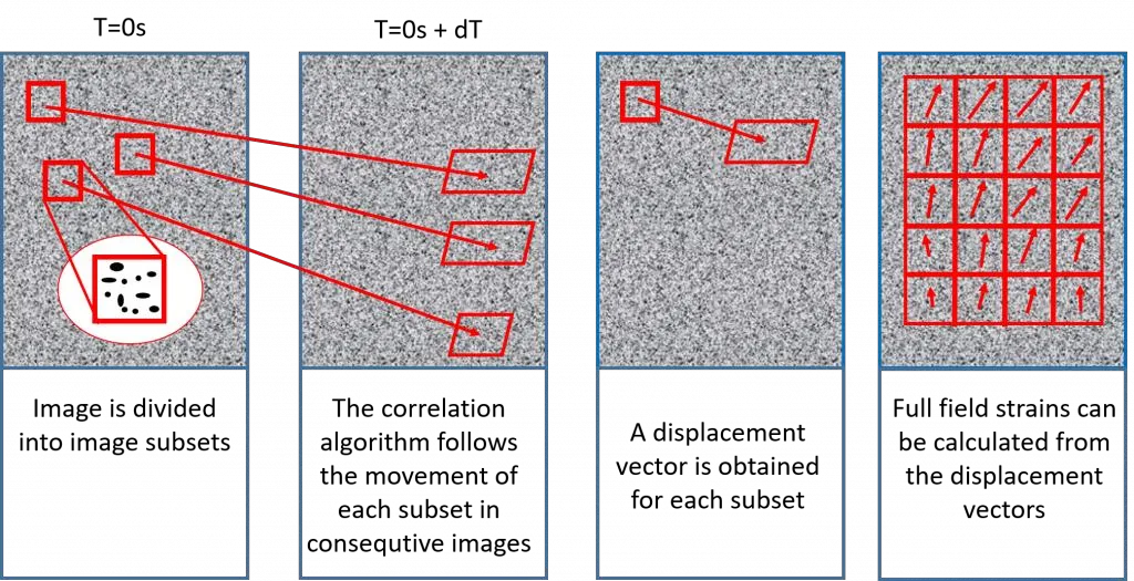
- Planned high-speed-camera tracking and Digital Image Correlation to convert a painted dot array into surface-strain measurements
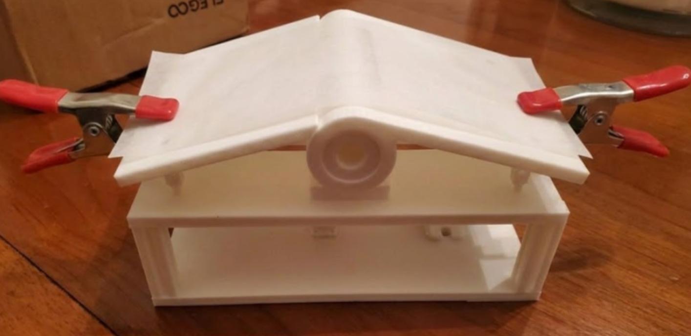
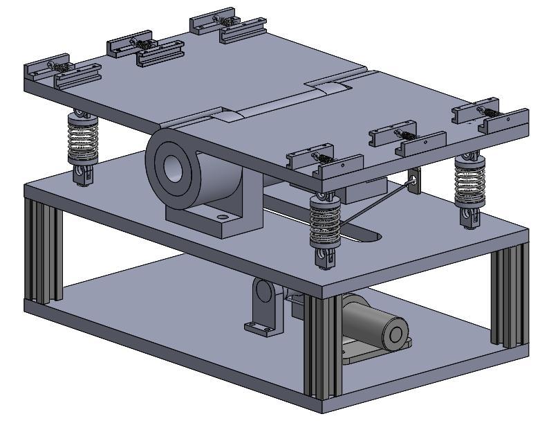
- Built the complete assembly in SolidWorks and produced a non-functional 3D-printed model to confirm the intended geometry and motion
Engineering Decisions & Trade-Offs
Electromagnetic linear actuation was selected because it eliminated a lubricated motor or gearbox inside the chamber. The trade-off was limited stroke and continuous force, so the linkage and spring preload had to be closed analytically before the concept could be considered feasible. Pulling both hinge plates with two cables also allowed one actuator to produce symmetric motion, reducing chamber hardware and feedthrough complexity.
The four spring clamps served two purposes: retaining the sample and limiting sudden axial loading as the hinge rotated. FFKM was chosen as an electrical-isolation layer compatible with low-outgassing requirements. For future measurement, Digital Image Correlation was selected over a single displacement sensor because a dot pattern and external camera could recover a full surface-strain field without placing additional instrumentation on the active sample.
Results & Validation
Modeled result For the report’s assumed 10 mm aluminum, 3 mm FFKM, and 5 mm Kapton stack, the analytical model predicted 19.65° rotation per hinge plate, a 291.5 mm effective bend radius, and 4.39% maximum tensile strain at the Kapton surface. Four springs required 10.0 N at full stroke. The selected VA-3070 actuator was rated for 15.7 N continuous and 52.8 N peak force, leaving a 5.7 N static continuous-force margin before cable friction, pulley losses, and dynamic loads.
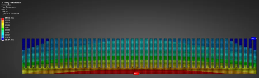
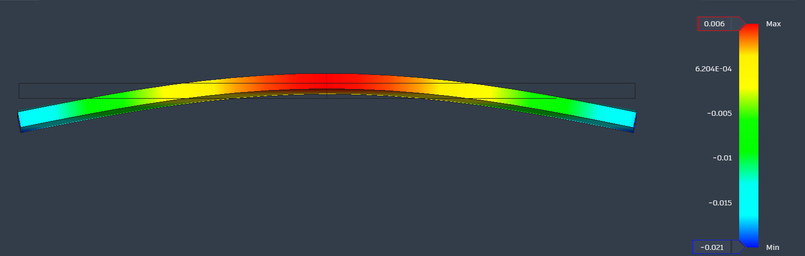
Preliminary FEA The displacement contour remained smooth across the sample instead of forming sharp local concentrations. A 3D-printed non-functional mockup then made the intended motion and packaging tangible, while also showing that the final hinge, clamps, and cable interfaces would require precision machining. Together, these checks support mechanical feasibility; they do not validate operation under vacuum or repeated dynamic cycling.
Impact, Limitations & Next Steps
The project moved the problem from a broad request for “dynamic EDS testing” to a traceable mechanism with defined geometry, force margin, material choices, deformation modes, and a measurement strategy. Its practical impact is a technically justified path from a conceptual research need toward a chamber-ready prototype, rather than a claim that the rig has already achieved TRL 4.
The 18.7× value is only the ratio of published Kapton ultimate elongation to the modeled surface strain; it is not a fatigue, tear-propagation, adhesion, or multilayer reliability factor. The next phase requires representative film-stack properties, cable-friction and dynamic-force measurements, precision fabrication, actuator-force and outgassing verification, electrical feedthrough design, chamber fit checks, and closed-loop cycle control. DIC should then be calibrated against known displacements before simultaneous vacuum, dust, electrical activation, and fatigue experiments are attempted.